Requirements:
 This video assumes you’ve got a Raspberry Pi that will work over Wi-Fi, a power source for the Pi, and that you’ve configured a microSD card for the Pi, installing the latest version of Raspbian Lite to work over Wi-Fi, and that you’ve installed CircuitPython libraries (videos demonstrate how to do this for use with the Adafruit Motor Hat and the Waveshare Motor Driver HAT). If you haven’t performed these steps, see videos in the tutorial at: videos for building an iOS-controlled Raspberry Pi robot, or the index of web-page tutorials that take you through the steps above.
This tutorial was written to install CircuitPython on a Pi as part of follow-along videos for building an iOS-controlled Raspberry Pi robot, but the steps below can be used to set up any Raspberry Pi on a network requiring a single password. The tutorial assumes you’re using a Mac (which will be needed if you’re going to use write an iOS app to control the robot).
Parts used in this tutorial include:
- A Raspberry Pi (it has been tested with the Pi Zero WH and the Pi 3 B+) and SD card, configured as indicated above, to work over WiFi, with at least Raspberian Stretch Lite OS installed, and CircuitPython installed.
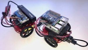
- The Adafruit Mini Round Robot Chassis – it comes with two wired DC motors and sells for less than $20 (I use the cheaper two layer bot, but this tutorial will work fine for the three tier bot, which is identical, save for one more deck plate for about $5 more).
- A Raspberry Pi Motor Hat prepared to work with your Pi. This talks to the Pi and controls the bot’s DC motors. This tutorial was tested using both the Adafruit DC & Stepper Motor HAT for Raspberry Pi – Mini Kit (about $22, requires soldering but is high quality, well-supported, and can run even more motors if you reuse parts for a future project) as well as the Waveshare Motor Driver HAT for Raspberry Pi, which I’ve seen online for as low as $13, has a nice Pi zero form factor (works with big Pis, too), won’t require soldering (we kludge connecting pins power wires) or for a more secure power connection, would need just two easy soldered connections, but the Waveshare also requires a bit of mild software tweaking (explained in this step-by-step tutorial) to work with CircuitPython.
- A power source for the Pi – a standard mobile phone charger like this one will work fine.
- A cable going from the charger to the Pi (the Pi has a mini-USB port, the charger likely has a regular USB port and a mini USB port – if you’re using a mobile phone charger, a cable like this likely came with it – here’s an example of what I’m using, and a short cable works well going from battery to bot, but make sure you have a miniUSB for the Pi, plus whatever is required by your battery).
- A separate battery pack and batteries to power the Motor HAT and motors. I recommend one with an on-off switch and pins at the end of the red and black wires, so it can be easily connected to the Motor HAT. Choose a 4 x AA case if you want the cheapest option, using single-use Alkaline AA batteries. If you want to use rechargeable AAs, you’ll need a 6 x AA case. Here’s a link to the < $3 4 x AA product used in the tutorial video.
- Four Male to Male jumper wires. One end will go into the red and black female connectors on each of the two motors, the other end will go into the terminals on the Motor HAT. You can get more than you need for less than $2.
- A screwdriver with a small flat head and small Phillips head.
Other things I use to complete this project:
- Toothpicks and small piece of foam from HAT package (for no-solder method) OR solder + soldering iron (for solder method). If you use soldering method, you may want to solder a terminal block (I think these are the right size) into the pins so you can easily attach and remove power wires, like you do with the motor wires.
- A small screwdriver with both Philips and flat heads. You can buy a really nice set that’ll likely serve you on all future projects for less than $11.
- Small pliers (needle-nose work well).
- Velcro Tape that’s sticky on one side. You’ll need some way to secure the parts to your robot chassis. I like Velcro tape – it’s secure, but also can be removed very quickly to do things like swap out batteries. You should have plenty for less than $3.
- A plastic case for the Raspberry Pi – while you could mount the Pi on foam tape, putting the Pi in a plastic case makes it easy to swap-out components without having any gunk residue on electronics. Chose one that’s right for the size of your Raspberry Pi model – you can pick one up for < $5.
- Electrical tape – useful for securing jumper wires. Available in most hardware stores, but you’ve probably got some in a drawer at home, right now.
Video:
Prefer video instruction? Use the follow-along YouTube video that covers the steps, below.
Step 1: Attach the Small Metal Panels to the Motors
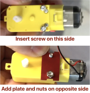
- In the previous video we attached the motor wires to jumper wires coming from the Waveshare DC Motor Driver Hat. Unplug these for now to make it easier to work with the motors.
- The motor axles come out two sides of the motor. On one you can see the head of a metal screw, the other has red and black wires coming out of it. Insert the screw through the hole on the side with the metal screw heads. Then insert the hole of the small red metal panel onto the tip of the screw that sticks out the opposite side (same size as the wires). Attach a nut and tighten. Repeat for both holes on both motors.
Step 2: Assemble the Wheels and Attach them to the Motors
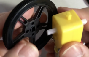 Each wheel has a rubber tread and a screw.
- Stretch rubber treads so they are each attached around a wheel.
- Fit one wheel on the white axle of each motor – use the side that does not have the small metal panel attached. There will be an oval indentation in the wheel that matches up with the end of the axle.
- Screw the tiny screw into the hole at the end of the wheel. You’ll need an itty bitty Phillips head screwdriver for this (the kit above has the perfect size).
Step 3: Attach the White Caster Ball and Brass Standoffs to the Bottom Plate of the Chassis
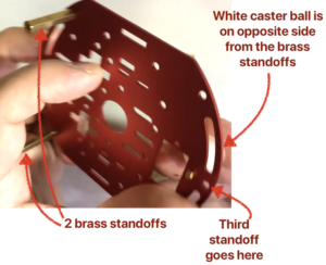 There is no proper top or bottom plate. All of the brass standoffs will attach regardless of how the plates are positioned. I only used three of the four brass standoffs, assembling using the following method:
- Attach the white cater ball (which acts as the third wheel) to the underside of one of the plates. Use the hole just behind the front-most hole. This will make it easier to attach the front brass standoff.
- Push a brass standoff screw through the front-most hole on the same side that the caster ball is on. Screw a brass standoff to opposite side so that the brass standoff will extend between the red metal chassis plates and is on the opposite side of the caster ball.
- Insert the remaining two screws and standoffs, attaching them to each “corner” holes on the side of the plate opposite the first standoff.
Step 4: Position the Motors and Attach the Top Chassis Plate
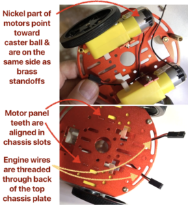 Now we’re going to create what looks like a “motor sandwich”, with the chassis plates as the “bread”. Position the motors so that the nickel-colored part (where wires come out) is pointing toward the white caster ball and the motors are on the same side as the brass standoffs. The small metal panels that you previously screwed to each motor have two “teeth” at each end – insert the teeth on one end into matching slots in the base chassis plate. It might be easier to flip the chassis plate over and look for the teeth to poke through from the opposite side to ensure alignment. Take care to make sure that you are not pinching the motor wires between the motor and the chassis plates.
- Once both motors plates are in the slots on the base chassis plate, align the top chassis plate so that the top “teeth” on each plate aligns with the slots in the top chassis plate. Again, this might be a bit tricky. Grab a friend or loved one to help out if you need an extra hand!
- Double check that all of the metal “teeth” on the small engine panels are aligned in slots on chassis plates (both top and bottom plate). When satisfied that alignments are correct, insert the remaining brass screws into the holes in the top chassis that are aligned with the brass standoffs. This might require that extra pair of hands to hold things together while you push or pull the brass standoffs to make sure they align with holes and can be properly screwed in. It might take a few tries, but everything should fit together.
- Thread the ends of the engine wires through the curved slots on the top chassis plate, at the end opposite where the caster ball and nickel parts of the engine are located.
Step 5: Use Velcro tape to secure the power supplies and Pi case
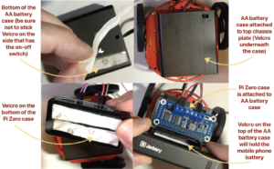 Using sticky-backed Velcro tape, position the two pieces of tape so the Velcro sides are stuck together and still-covered sticky-backs face out. Measure the Velcro tape considering the length of objects that are to be stuck together. Make sure that attaching components won’t rub against wheels or cover on/off switches. Then peel the protective layer off one of the sticky sides, stick the tape to the surface of the smaller object, then peel the protection off the other sticky side and push the object into place. You won’t be separating the Velcro strips until after items have been stuck together and have had time to adhere. It’s OK to keep everything stuck together until you need to peel apart the Velcro-adhered pieces for something like replacing batteries.
Step 6: Attach Pi and Motor Wiring
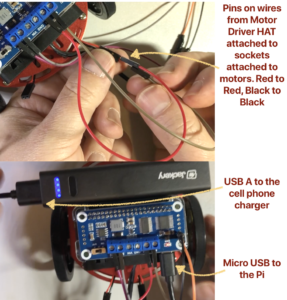 Slide the loose ends of the male pins of the jumper wires coming from the Motor HAT into the female sockets at the end of each motor wire. Make sure that red wires match with red wires, black with black, and that the pair of red-black wires in each terminal matches with a pair of red-black sockets coming from the same motor.
- Assuming that you’re using a mobile phone battery to power the Pi, plug the larger USB-A (standard) end into the battery, and the micro USB end into the power port on the Pi. Double check everything is wired and secured.
Step 7: Create a Test Program in CircuitPython to Test the Bot
- Power up your Raspberry Pi.
Log into your Pi.
- Launch the Terminal program on your Mac by pressing Command-Space to launch Spotlight, then type Terminal, and press the return key.
- Log into your Pi using the command below replacing hostname with your Pi’s hostname, then press the return key.
ssh pi@hostname.local
- Enter your Pi’s password when prompted, and press the return key.
Create the firstroadtest.py python program
- From the command prompt, type the following command, then press the return key, to begin creating a file named firstroadtest.py using nano.
nano firstroadtest.py
- Visit the URL: https://github.com/gallaugher/pibot
- Click the link for the file named firstroadtest.py. A page containing python code will open.
- Copy the python code on this page, return to the Terminal, and paste this code into nano.
The code, as listed, will work with the Adafruit DC and Stepper Motor HAT, but if you are using the Waveshare Motor Driver HAT, then we need to make one additional change (skip the next four bullet points if you’re using an Adafruit HAT or other product that is natively compatible with CircuitPython).
- Use the down-arrow until you find the line containing the code that reads:
kit = MotorKit()
and modify this code so it reads like line below – you can just position your cursor between the two parentheses and type 0x40. Note, those are both zeros and not the letter o.kit = MotorKit(0x40)
- Type Control-X to quit nano.
- Type “Y” when asked if you’d like to save the file.
- Press the return key after the file name and you’ll be returned to the command prompt. You’ve just updated the firstroadtest.py to work with the Waveshare Motor Driver HAT.
Now test run the program and test your bot!
- Make sure your MotorHat battery pack is also turned on (the AA battery pack in the examples above).
- From the command prompt, type the following command, then press the return key
python3 firstroadtest.py
Your bot should tool around nicely. Congratulations – you’re officially a bot builder!
Up next – install moquitto software on your Raspberry Pi so you’ll be able to send messages and control the bot from an app.